Beranda
/ Timer And Contactor R Relay Diagram - How to wire a contactor and overload - Direct Online ... / Coil data chart (at20 c).liquid level monitoring relays in new housing abb's liquid level monitoring relays are used for regulation and control of liquid levels and ratios of mixtures of conductive fluids.
Timer And Contactor R Relay Diagram - How to wire a contactor and overload - Direct Online ... / Coil data chart (at20 c).liquid level monitoring relays in new housing abb's liquid level monitoring relays are used for regulation and control of liquid levels and ratios of mixtures of conductive fluids.
Insurance Gas/Electricity Loans Mortgage Attorney Lawyer Donate Conference Call Degree Credit Treatment Software Classes Recovery Trading Rehab Hosting Transfer Cord Blood Claim compensation mesothelioma mesothelioma attorney Houston car accident lawyer moreno valley can you sue a doctor for wrong diagnosis doctorate in security top online doctoral programs in business educational leadership doctoral programs online car accident doctor atlanta car accident doctor atlanta accident attorney rancho Cucamonga truck accident attorney san Antonio ONLINE BUSINESS DEGREE PROGRAMS ACCREDITED online accredited psychology degree masters degree in human resources online public administration masters degree online bitcoin merchant account bitcoin merchant services compare car insurance auto insurance troy mi seo explanation digital marketing degree floridaseo company fitness showrooms stamfordct how to work more efficiently seowordpress tips meaning of seo what is an seo what does an seo do what seo stands for best seotips google seo advice seo steps, The secure cloud-based platform for smart service delivery. Safelink is used by legal, professional and financial services to protect sensitive information, accelerate business processes and increase productivity. Use Safelink to collaborate securely with clients, colleagues and external parties. Safelink has a menu of workspace types with advanced features for dispute resolution, running deals and customised client portal creation. All data is encrypted (at rest and in transit and you retain your own encryption keys. Our titan security framework ensures your data is secure and you even have the option to choose your own data location from Channel Islands, London (UK), Dublin (EU), Australia.
Timer And Contactor R Relay Diagram - How to wire a contactor and overload - Direct Online ... / Coil data chart (at20 c).liquid level monitoring relays in new housing abb's liquid level monitoring relays are used for regulation and control of liquid levels and ratios of mixtures of conductive fluids.. Timer has two element, timer and relay. This articles covers working and the relays and contactors: Preset time can be as low as milliseconds to hours and even days but usually, in the industrial control system. The af contactor technology revolutionizes how we use contactors and allows use in all parts of the world and in all network conditions. Output relay 'r' will energise as soon as the supply is applied to the timer if control switch 's' closed, and will start to time out unless control at this.
How to make it work as i want, or the timer selection is probably not correct? A wiring diagram is a streamlined traditional photographic representation of an electrical circuit. These diagrams are meant to be conceptual but often we try to take them literally. This is used to control the 'star' contactor. Relays, contactors, and magnetic motor starters normally have more than one set of auxiliary contacts.
Joslyn Clark 7001-5230-82 DC Drive Contactor 40 Amp 24 VDC ... from assets.suredone.com A 12v relay is used to drive the ac load connected at the output. Use these tips to learn how to wire a contactor. Operationally, it works the same way. Using an adapter plate, you can also mount it for standalone use. Omron safety relay wiring diagram gallery. Used in circuits with lower ampacity. Assortment of timer relay wiring diagram. Nema heavy duty relays allen bradley.
The main difference between the contactor and relay is that, contactor is a high power device while relay is a low power device.
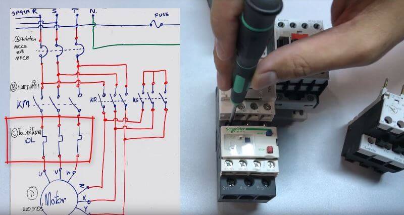
I have the contactor and timer sketch below, hope its clear enough. The 555 timer, designed by hans camenzind in 1971. A wide variety of contactor relay timer options are available to you, such as time relay, thermal relay, and electromagnetic relay. Ql series electromechanical relay specifications. Timer and contactor r relay diagram : This countdown timer can be set up to 100 hours. Coil data chart (at20 c).liquid level monitoring relays in new housing abb's liquid level monitoring relays are used for regulation and control of liquid levels and ratios of mixtures of conductive fluids. This articles covers working and the relays and contactors: A wiring diagram is a streamlined traditional photographic representation of an electrical circuit. Assortment of timer relay wiring diagram. Engineering electrical diagram contactor and timer. Contactors appear nearly identical to relays on schematic diagrams. With help of following timing diagram we can easily understand working of timer.
Engineering electrical diagram contactor and timer. Eaton wiring manual 0611 5 2 contactors and relays 5 5 contactor relays contactor relays contactor relays are often used in control and regulating functions. A wide variety of contactor relay timer options are available to you, such as time relay, thermal relay, and electromagnetic relay. the wa4 mechanical latching unit for af tactors can be easily converted into compact latched contactors. A wiring diagram is a streamlined traditional photographic representation of an electrical circuit.
Payne Hvac Capacitor Wiring Diagram from lh6.googleusercontent.com Use these tips to learn how to wire a contactor. Using an adapter plate, you can also mount it for standalone use. Engineering electrical diagram contactor and timer. A bus bar is placed over the connection where the other set would be, as shown in figure 6. Each relay activation will cause the light to toggle. These diagrams are meant to be conceptual but often we try to take them literally. This countdown timer can be set up to 100 hours. The as contactor is efficient and allows you to optimize your equipment design.
These contacts may appear at several different locations in the line diagram.
Contactors appear nearly identical to relays on schematic diagrams. Coil data chart (at20 c).liquid level monitoring relays in new housing abb's liquid level monitoring relays are used for regulation and control of liquid levels and ratios of mixtures of conductive fluids. 3 pole contactor without base contact 4 pole contactor with 4 n.o. So it may be the motor switch, or it may be an actual latching google on/off contactor schematics and you will get some good wiring diagrams. This creates a basic memory function the relay ' remembers'. Contactors are switching devices used to control power flow to any load. Power poles 4 pole contactor with 2 n.o./2 n.c. Larger when compared to relays: A time delay relay consists of a normal electromechanical relay along with a control circuit to control the relay operation and timing. 240 volts ac and 480 volts ac are commonly used for these large pieces of. 4 pole control relay with 4 n.o. Use these tips to learn how to wire a contactor. This articles covers working and the relays and contactors:
Power poles 3 pole reversing contactor set. Power poles 4 pole contactor with 2 n.o./2 n.c. Contactors appear nearly identical to relays on schematic diagrams. Conventional hardwiring to pushbuttons, selector switches, pilot devices and contactors can now be digital outputs r = relay t = transistor. Larger when compared to relays:
The Beginner's Guide to Wiring a Star-Delta Circuit ... from www.factomart.com.sg Omron safety relay wiring diagram gallery. Timer has two element, timer and relay. This is used to control the 'star' contactor. Contacts 4 pole control relay with 2 n.o. Engineering electrical diagram contactor and timer. Output relay 'r' will energise as soon as the supply is applied to the timer if control switch 's' closed, and will start to time out unless control at this. Operationally, it works the same way. The 555 timer, designed by hans camenzind in 1971.
Power poles 4 pole contactor with 2 n.o./2 n.c.
Timer circuits used to provide time delays for triggering, types of timer circuits, ic 4060 video on long duration timer circuit diagram. This countdown timer can be set up to 100 hours. A time delay relay consists of a normal electromechanical relay along with a control circuit to control the relay operation and timing. Output relay 'r' will energise as soon as the supply is applied to the timer if control switch 's' closed, and will start to time out unless control at this. The main difference between the contactor and relay is that, contactor is a high power device while relay is a low power device. 240 volts ac and 480 volts ac are commonly used for these large pieces of. Relays are switching devices used in any control circuit for checking a condition or multiplying the number of contacts available. 4 pole control relay with 4 n.o. Figure 16 at the end of this chapter includes many other symbols for switches and relays. It shows the components of the circuit as simplified shapes, and also the power as well as signal connections in between the gadgets. Contactors appear nearly identical to relays on schematic diagrams. Clap switch circuit using ic 555 timer & without timer. Such relays are called time delay relays.